Input Devices
Individual assignment:
Introduction
Input devices are all about sensors in fabacademy course . Through sensors we connect the outside world into microcontrollers. Neils class on input devices gives me an overview about different types of sensors for sensing different parameters.
For completing this week's assignment I decided to choose an ultrasonic sensor as my input device. I intend to use this sensor for my final project.
Ultrasonic sensor
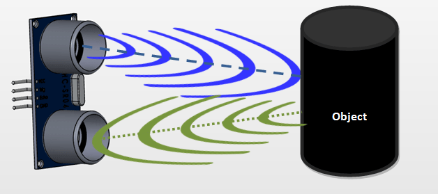
It emits ultrasonic sound waves and detects the reflected sound waves and converts this sound into electronic signals. Ultrasonic sensors are mainly used to detect the distance of the target body. It can be used as proximity sensor
Ultrasonic sensors have the transmitter, which emits the sound using piezoelectric crystals and the receiver, which detects the reflected sound wave from the target object.
How Ultrasonic sensors calculate distance?
The sensor measures the time it takes between the transmission and reception of sound waves.
The formula for this calculation is D = (T x C) 1/2
Where D is the distance in meter,
T is the time in second, and
C is the speed of sound i.e. 340 m/s)
When compared with infrared sensors, ultrasound sensors are less likely to get interference with daylight, smoke, and airborne particles. But there is a chance of getting interference with certain sound frequencies .
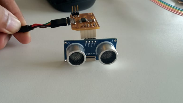
(HC-SR04) ULTRASONIC SENSOR
I used an ultrasonic sensor HC - SR04 module commonly available in the market. It works on the same principle mentioned above. This can measure a distance of range from 2 cm to 400 cm with an accuracy of 3mm. The HC- SR04 modules consist of a transmitter, receiver and control circuit.
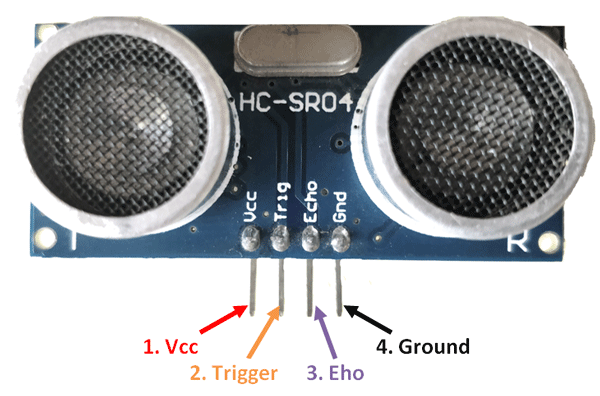
Pin configuration
Electric Features
Datasheet for Ultrasonic Sensor- (HS-SR4)
PCB Design
I started with PCB design using EAGLE software. Referred by Week6- electronic design documentation for designing my PCB.
Components used
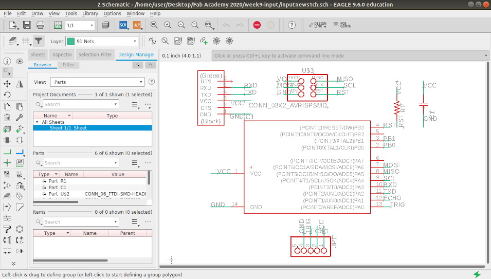
After adding the components connect the pins using NET Tool and move to board mode.
Before going to autoroute, We need to go to 'design rule' from 'EDIT' and change value from 6 mills to 16 mills (1/64 trace tool for PCB milling is used)
After autorouting, I manually connected the remaining traces.
I followed the steps in my week_6 documentation
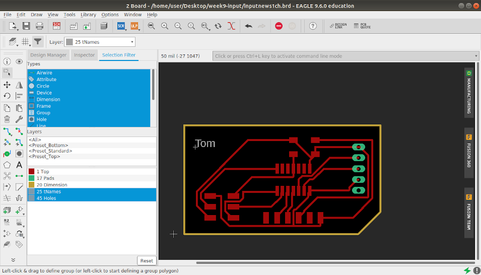
My Trace Images required for milling operation.
.png)
For Holes
.png)
For Boarder
.png)
Milling
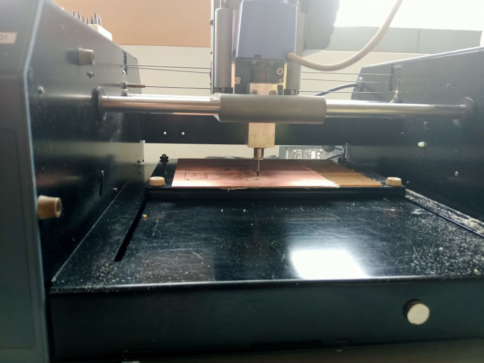
After milling my board' s trace was a little rough due to small irregularities in the drill bit. I used sandpaper/glass paper to get smooth traces.
Soldering
My PCB after soldering all components to the board
Programming
      #include < SoftwareSerial.h >

        #define Trig 1 //Ultarsonic Trig Pin Connected to pin 13 of ATtiny44
        #define Echo  0 //Ultarsonic Echo Pin Connected to pin 12 of ATtiny44

        #define RX    2   //TX pin of ATtiny44
        #define TX    3  //RX pin of ATtiny44

        SoftwareSerial window(RX, TX); //initialize 'window' as Software Serial

        void setup()
        {
          pinMode(Trig, OUTPUT); //set trig pin as OUTPUT
          pinMode(Echo, INPUT); //set echo pin as INPUT

          window.begin(9600);   //initialize software Serial in 9600 bit's per second

        }

        void loop()
        {

        long duration, distance;
        digitalWrite(Trig, LOW);
        delayMicroseconds(2);
        digitalWrite(Trig, HIGH);
        delayMicroseconds(10);
        digitalWrite(Trig, LOW);
        duration = pulseIn(Echo, HIGH);
        distance = (duration/2) / 29.1;
        window.print("Distance :");
        window.print(distance);
        window.println(" CM");

        delay(100);
        }
Sensor Working Video
GROUP ASSIGNMENT
Link to group assignment page
FILES